Discover our 24-bit Class-D Audio Dac, silicon proven |
Dolphin Semiconductor’s on-chip setup slack monitors flag, in real time, when the timing margin of your digital design falls below a programmable threshold. That lets the system lower power or raise frequency, prevent timing-induced data corruption, and track ageing across the product’s life, all from a purely soft, standard-cell IP.
Dolphin’s silicon monitoring solution connects setup slack monitors to the critical paths of your digital design. Each monitor raises a flag when a real path’s timing margin falls below a threshold, continuously while the chip operates, not just pass or fail at test. Several threshold levels can be monitored at once, so the system acts on the actual margin of its own paths instead of worst-case guard bands. And because the monitors sit on real paths, they capture the combined effect of process, voltage, temperature and ageing (PVTA) where it matters: at data level.
Most chips already carry temperature sensors, supply monitors or ring oscillators. Those measure operating conditions. None of them looks at the quantity that decides whether a path fails: the slack left on the path that actually limits the design. A setup slack monitor watches that quantity directly, on the path itself, with no calibration look-up table.
Figures from the Silicon Monitoring Product Brief, Rev 2.1. Area overhead is 0.1% of gate count for cores up to 500 k flip-flops, and 0.035% above 3 M flip-flops.
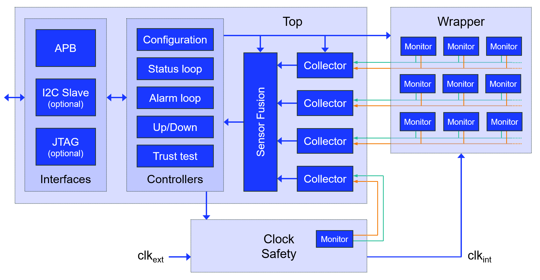
Block diagram: setup slack monitors distributed across the design, with the control, interface and safety subblocks that ship with the IP.
One monitoring platform, four results for your design.
Closing the loop lowers the supply voltage until the monitors flag that margin has reached its threshold (the lowest safe level for that die) instead of guard-banding for the worst combination of corner, droop, temperature and end-of-life ageing. The same recovered margin can be spent on frequency instead.
Best fit: Power-constrained HPC, consumer CPU and edge-AI SoCs
Power saving vs PVT-based AVS loop
When a supply droop or thermal excursion collapses the margin, an ultra-fast safety mechanism responds in under 3 clock cycles, before a setup violation can silently corrupt data. ECC protects memories; it does not cover logic timing. This does.
Best fit: HPC, networking infrastructure and safety-relevant automotive SoCs
Voltage-drop mitigation
Stepping the programmable threshold at production test records a baseline for each die; repeating it periodically in the field gives every unit its own ageing trajectory, instead of one assumed allowance applied to the whole fleet. Replace units on their actual condition, not on the calendar.
Best fit: Long-lifetime automotive and industrial systems
Per-die margin data reduces overdesign and specification spread, supports binning and outlier screening, and brings the speed verdict forward to wafer sort, so too-slow dice are caught before packaging money is spent.
Best fit: HPC and chiplet-based designs, where packaging cost is high
Designed to drop into an existing flow, with no analog content to port.
Purely soft IP. Synthesizable RTL built entirely from standard cells, with no analog macro to port, characterise or re-qualify.
Automated integration. Provided TCL scripts automate insertion, compatible with most EDA flows.
Path selection at P&R. Monitored paths are chosen from your own static timing analysis, on criteria including activity, IR-drop and data sensitivity, so results sit closer to silicon.
No impact on the critical path. The worst paths are deliberately left uninstrumented. Monitors sit on near-critical paths, so timing is unaffected.
Node and foundry portable. With no analog content, the IP moves across process nodes and foundries with a re-synthesis, including mature nodes.
Three interfaces: APB, I2C and JTAG. JTAG serves production test. In the field, the monitors are read over APB by on-board firmware or over I2C by a separate board controller, so the debug port can be permanently disabled.
Calibration-free. No look-up table to build or maintain.
Test-friendly. Silicon validation runs through scan: no dedicated pin, a standard digital tester is enough.
Complete platform. Ships with control, interface and safety subblocks, and supports register-to-memory paths.
Each application is matched to the requirement the IP addresses.
Lower power Data protection Production cost
At the highest compute densities, supply droop and IR-drop dominate the guard band. Slack monitoring brings voltage down safely, ultra-fast protection covers the droop events that remain, and a wafer-level speed verdict keeps too-slow dice out of expensive chiplet packages.
Lower power
Every recovered millivolt becomes battery life or thermal headroom. Setting voltage from each die’s actual margin rather than the worst-case corner delivers it on every unit.
Predictive maintenance Data protection
Long service lives and wide temperature ranges make ageing and corner coverage the dominant concerns. Per-unit ageing trajectories support maintenance on condition, and ultra-fast protection supports functional-safety goals.
Lower power
In fanless and battery-powered modules, power is the product. Recovered guard band converts directly into performance per watt inside a fixed thermal envelope.
Reliability. Margin erosion is detected before it becomes a failure, and ultra-fast protection stops the timing faults that do occur from corrupting data.
Efficiency. Acting on each die’s actual margin instead of worst-case guard bands recovers power or frequency from the same design.
Yield & field reliability. Per-die margin data tightens specification spread and catches outliers before they become field failures.
Root-cause analysis. Threshold events and slack flags, readable over APB or I2C, support root-cause analysis and predictive maintenance across the product’s lifetime.
The setup slack of real critical paths: the time left between when data arrives at a flip-flop and when that flip-flop needs it. Each monitor raises a flag whenever that slack falls below a programmable threshold, continuously while the chip operates, so process, voltage, temperature and ageing effects are seen directly at data level rather than inferred.
Those measure operating conditions: temperature, voltage, or how fast a generic loop of gates oscillates. None of them looks at the slack left on the path that actually limits the design. Turning a ring-oscillator frequency into path slack is a modelling step with wide uncertainty, and it needs calibration. Setup slack monitors watch the real quantity directly on the path, with no look-up table.
No. The worst paths are deliberately left uninstrumented. Monitors sit on near-critical paths, so the functional logic is untouched and the impact on performance is negligible.
The power controller lowers the supply voltage until the monitors flag that timing margin has reached its threshold, so voltage settles at the lowest safe level for that die, rather than at a worst-case guard band. Compared with open-loop voltage regulation, the timing regulation loop saves more than 15% power; compared with a PVT-based AVS loop, more than 10%. Learn more about adaptive voltage scaling.
Dolphin licenses per project, with the option of per-unit royalties depending on the volume. A licence covers the deliverable set needed for integration: synthesizable RTL, TCL integration scripts, models, documentation and integration support. Terms are set with the field engineering team during the technical evaluation.
© 2024 Copyright by Dolphin Semiconductor – All Rights Reserved
To provide the best experiences, we use technologies like cookies to store and/or access device information. Consenting to these technologies will allow us to process data such as browsing behavior or unique IDs on this site. Not consenting or withdrawing consent may negatively affect certain features and functions.